Blink an LED
Step 9Move to a GPIO pin
Move the wire that was going to your board's 3.3V pin over to a GPIO pin instead. The diagram below uses GP16, but check your board's pinout diagram since pin names vary between boards.
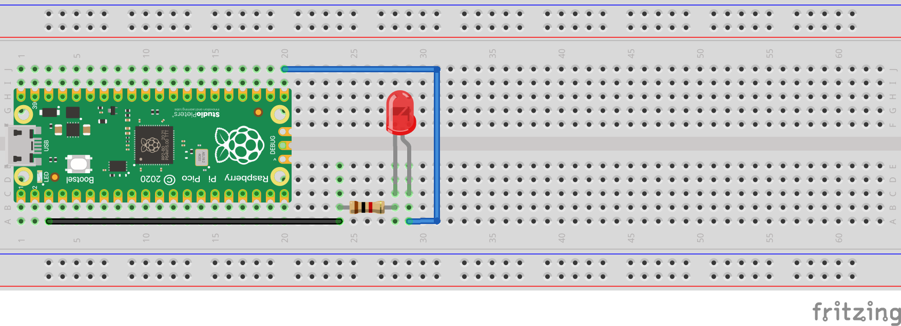
Wire color
Notice that we changed the wire color to show we are connected to a pin instead of directly to power. The color that you use for a non power pin is really up to you, and again, using a color other than red is not strictly necessary. You should try to vary the colors of wire you are using as much as possible. I can tell you from experience, however, that figuring out which of 10 yellow wires I have connected wrong is not very easy!
GPIO?
GPIO stands for "general purpose input/output," pins your code can control directly, either reading a signal (input) or sending one (output). Everything else about the wiring from the last step stays the same.
What the code is doing?
The comments in the code below walk through what each line does. The imports bring in code other people wrote so you don't have to write it yourself, the two lines after that set up a variable representing the LED pin and configure it as an output, and the loop turns it on and off with a pause in between. if statements and writing your own functions (def) will show up once future steps start making decisions based on sensor input, rather than just repeating on a timer like this one does.
Click Connect, then Run on Device, and your LED should start blinking. Try changing the two time.sleep() values to speed it up or slow it down, and run it again to see the change immediately.