Light Up an LED
Step 8Time to build a circuit
Time to move off the console and into an actual circuit. Before wiring anything, here are a few basics.
Breadboards
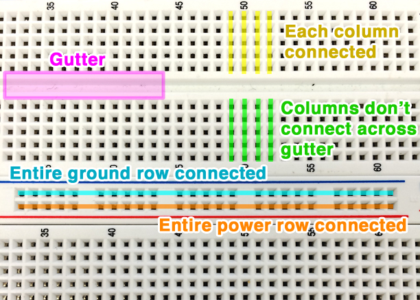
The columns of holes down each side of a breadboard are connected in short strips. This lets you connect components together without any soldering. Columns do not connect horizontally, and there is also usually a gap in the middle of the board (the gutter) that further separates the columns. Some boards will also have power and ground rails along the sides, which are connected all the way from top to bottom, so you can get power anywhere you need it.
Resistors
Before we can power the LED, we need to understand what a resistor is and how to use one so we don't send too much power through the LED. A resistor does what it says and resists the flow of electricity. There are many reasons we might want to do that, but for our LED all you need to understand is that it prevents the LED from getting too much power and breaking. The amount of resistance a resistor has is measured in something called Ohms, represented by the symbol Ω. The higher the number of Ohms, the more the resistor resists the flow of electricity.
LEDs have polarity
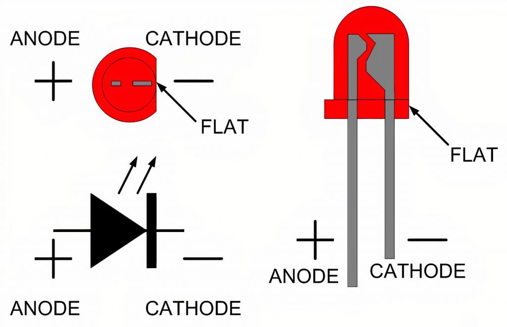
Power only flows through an LED one way, from the + side to the -. The longer leg is called the anode (+) and the shorter leg is the cathode (-). There is also usually a flat side on the LED body that marks the cathode too.
A circuit
Everything that uses power needs to be in something called a circuit. A circuit just means that there is an uninterrupted path from some voltage source (+) to a voltage sink or ground (-). So for our LED example, we need to make sure that we connect the voltage source to ground through the LED.
Determining the pins for your microcontroller
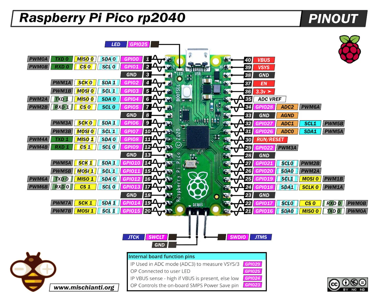
Different microcontrollers have different layouts for their pins. Some are well labeled and others not so much. If you do not see good labels on your microcontroller, google "(the name of your microcontroller) pinout" and look for an image like this.
Building our circuit
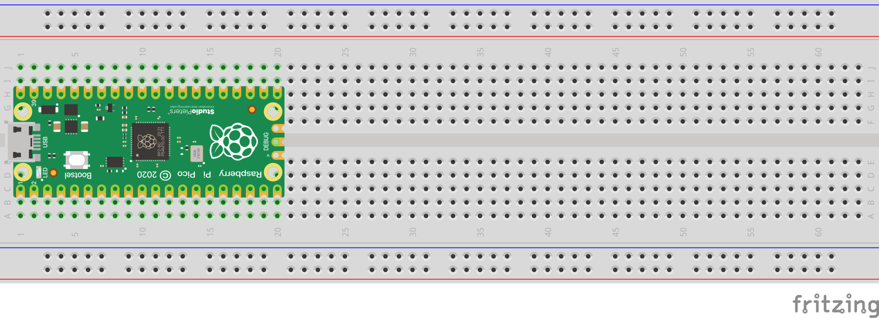
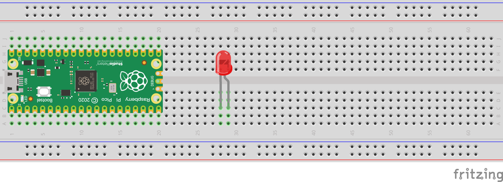
- Push your microcontroller into the breadboard as far as the pins can go.
- You may have to put a good amount of force. Don't worry, you will not break it!
- Notice that the pins are on either side of the break in the middle, so they are not connected.
- The microcontroller can go anywhere on the board, but I prefer to keep it at the end with the USB port sticking out to make it easier to use.
- Push the LED into the breadboard.
- Make sure the legs are in different columns or separated by the gap in the middle.
- Make sure neither leg shares a column with any pin of the microcontroller.
- Remember which leg is + and which leg is -.
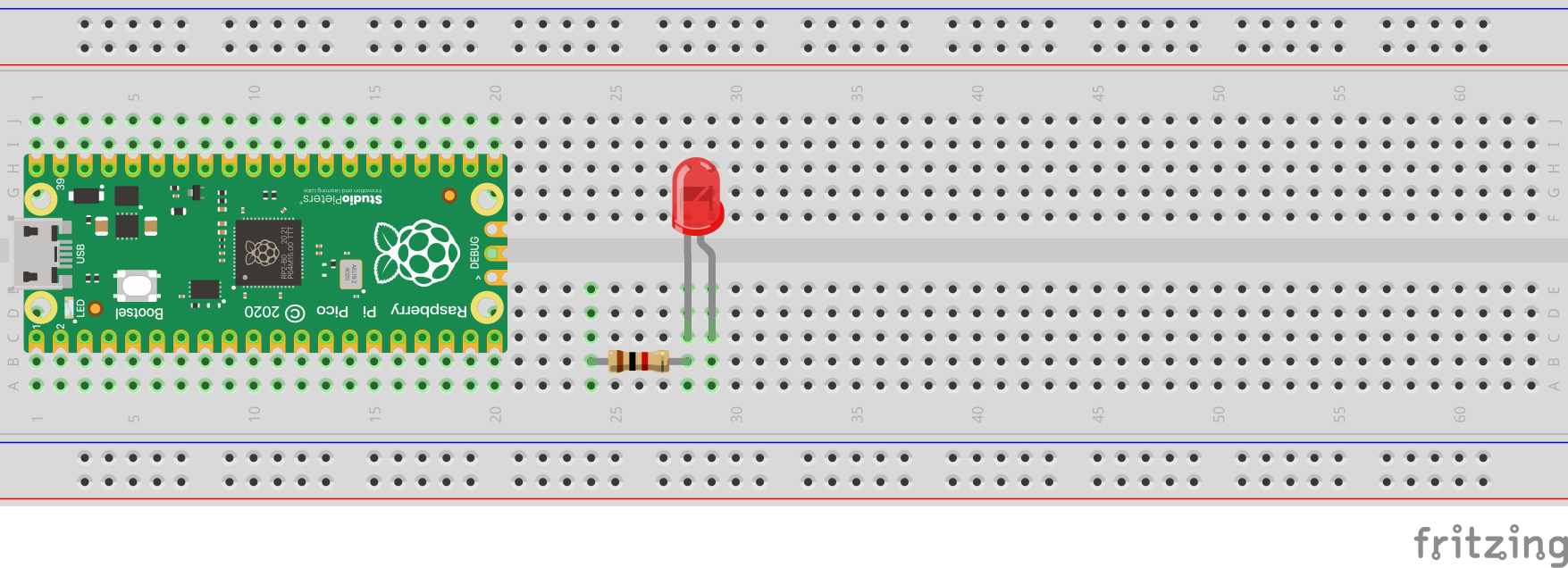
- Push the resistor into the breadboard with one leg in the same column as the - leg of the LED.
- Again make sure the legs are in different columns or separated by the gap in the middle.
- Make sure neither leg shares a column with any pin of the microcontroller.
- Resistors do not have a direction.
- Connect the other leg of the resistor to ground on your microcontroller with a jumper wire.
- Ground pins will be labeled something like
GND. 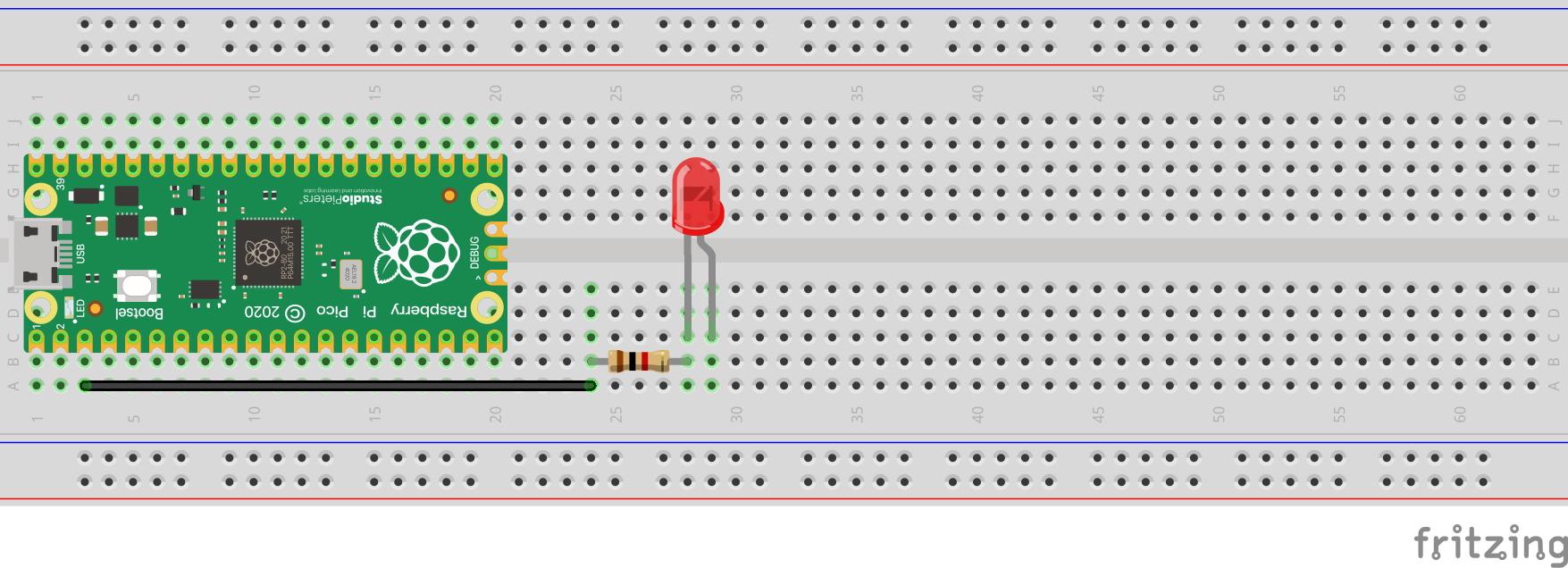
- Ground pins will be labeled something like
- Connect the
3.3Vpin of your microcontroller to the + leg of the LED with a jumper wire.- It may be labeled slightly differently.
- If you only have a
5Vpin, that will work as well, just make sure to use a larger resistor. - Your
5Vpin may also be labeledVSYSor something else. 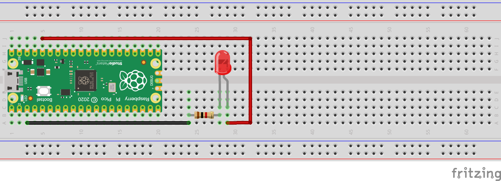
If the LED lights up when the board is powered, the circuit is good! If it does not light up, try switching around the legs of the LED. Next step is controlling it from code instead of wiring it straight to power.
A Note on wire colors
You may have noticed that in the diagrams we used black and red wires. In general black is used to represent negative (-) and red is for positive (+). This is not strictly necessary but when you start to have many jumper wires plugged into your breadboard, it is convenient to be able to tell them apart by color and know that you are not accidentally sending power to the wrong thing!
A Note on resistor values
Different color LEDs need different amounts of power, so the exact resistor value depends on your specific LED and power source. Use the LED Resistor Calculator to get it exact, or just use a safely oversized resistor (1kΩ or higher) if you'd rather not calculate anything. It'll always protect the LED, just with less brightness. For the full explanation of why resistors matter here, check out What Is a Resistor? and Ohm's Law Explained.